CNC waterjet cutting. Precision without heat.
The preferred technology when material quality and zero deformation are required.
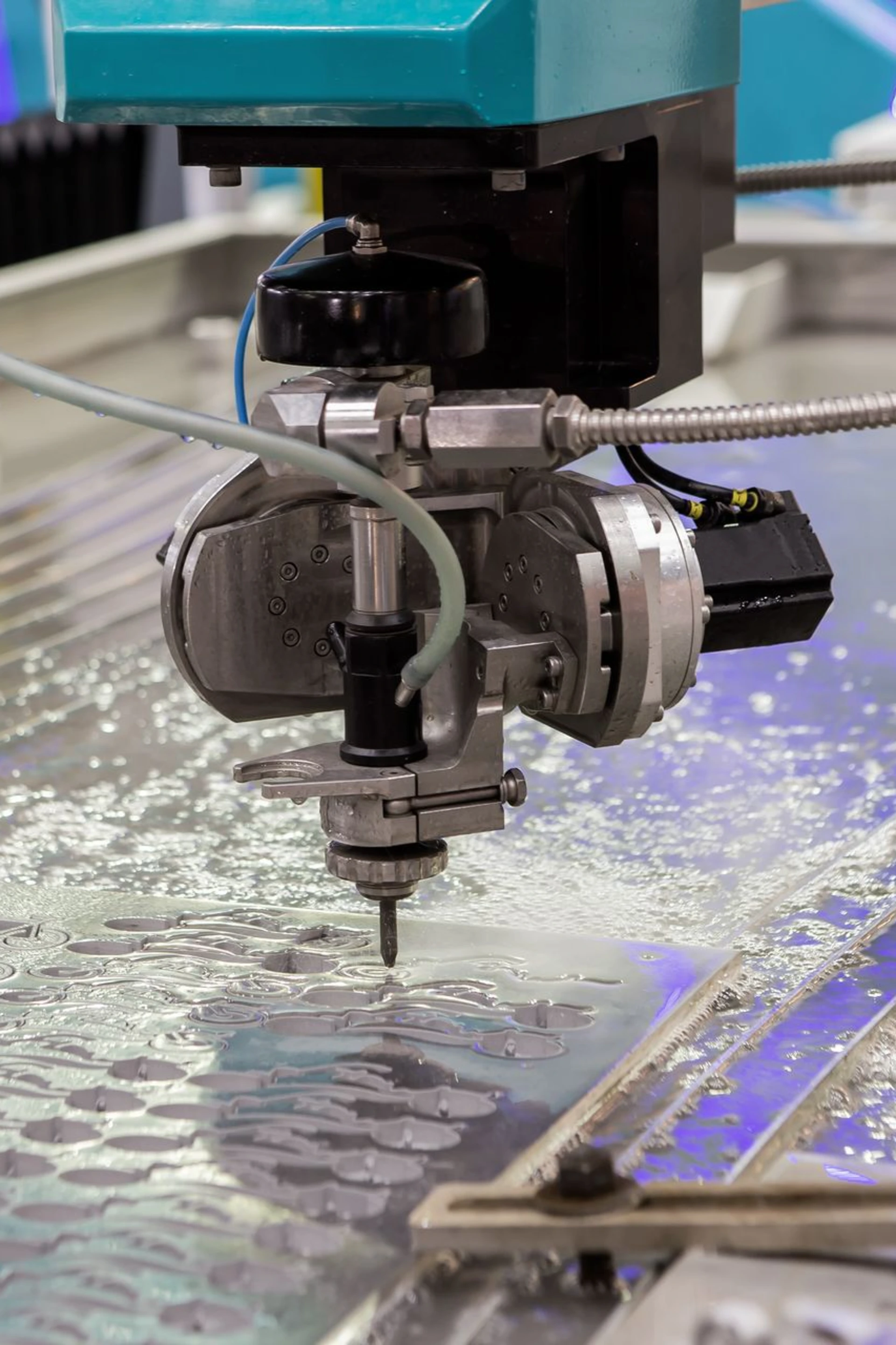
What is CNC waterjet cutting and how is it used in an industrial environment?
High pressure combined with controlled flow for demanding materials.
A pump generates pressures above 4,000 bar, directing the jet through a nozzle to erode the material. This is the basis of CNC waterjet cutting. The process can use pure water for soft materials such as plastics, paper, or food, or water with abrasive for metals such as steel, aluminum, and titanium. It is suitable for metals, ceramics, plastics, and composite materials.
By not generating heat or affecting the material's structure, this cutting technology waterjet is ideal for parts that require high precision, without deformation and with burr-free finishes, and it also supports multilayer cutting or thick materials.
Due to these characteristics, waterjet cutting is used in sectors where the integrity of the material and the precision of the cut are critical, such as:
Industrial machinery manufacturing
Composite and advanced materials manufacturing
When to choose waterjet cutting
Heat-sensitive materials
High-value parts where deformation is not acceptable
Thick materials or complex compositions
What problems it avoids
Rejection due to thermal alteration
Secondary grinding or finishing operations
Internal stresses in the part
Types of waterjet cutting
Both pure waterjet and abrasive waterjet are part of advanced cutting technologies that do not create a heat-affected zone and complement processes such as laser cutting or CNC punching.
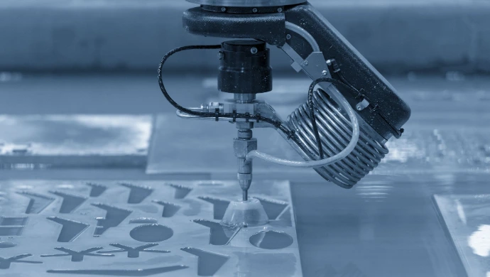
Pure waterjet
Uses only water. Suitable for soft materials or processes requiring cleanliness and no thermal impact.
Abrasive waterjet
Uses abrasive particles, typically garnet, to cut metals, glass, ceramics, and hard composites. This is the most common option in metalworking.
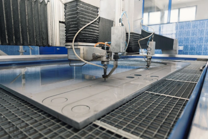
2D/3D CNC waterjet cutting
Ability to make straight or angled cuts (5-axis head), suitable for complex geometries and assembled parts.
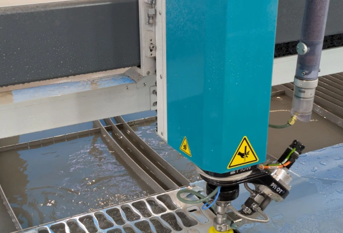
CAD/CAM Guide + Waterjet
In waterjet, the difference between cutting and efficient production is marked by the software
Its direct impact on reducing waste, downtime, and errors improves ROI and ensures quality in every cut. Choosing a powerful system will allow any machine to perform at the highest level and easily integrate into digital and scalable environments.
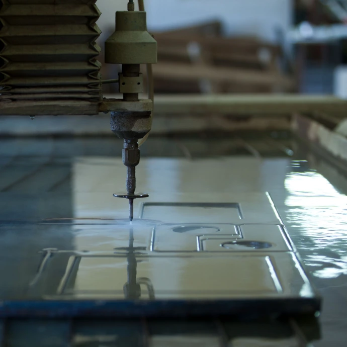
Compatible software with your waterjet environments, today and in the future
Avoid technological lock-ins and dependencies on a single machine manufacturer
In industrial waterjet cutting, the software must integrate with your machine. Each system uses different configurations of heads, pumps, and controllers.
If you production includes multiple technologies such as combined waterjet with laser and plasma, you need a multi-technology and scalable solution. This way, you maintain a unified workflow without duplicating systems.
A single platform connects CAD/CAM, MES, and ERP to manage the entire process within the factory’s digital environment.
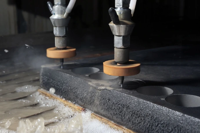
Hydraulic and process control in water cutting
Pressure, abrasive flow, and cutting speed must be precisely controlled
Dynamic speed adaptation throughout the path also helps improve process stability and reduce cutting defects.
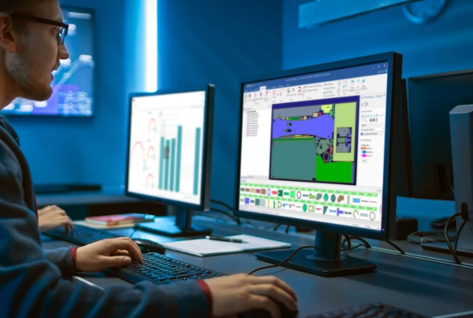
Optimized nesting for waterjet cutting
Efficient material use and reduced waste
The nesting in waterjet must consider irregular geometries, reusable scraps, and minimum spacing between parts, especially when working with high-cost materials.
Additionally, the software can also adjust automatically cutting speeds in critical nesting areas to maintain edge quality even when multiple parts are cut in sequence.
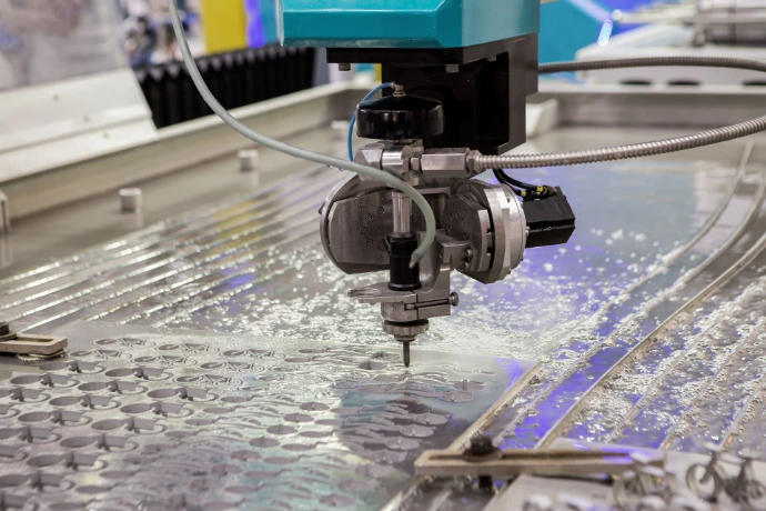
Management of drilling and safe toolpaths
Clean entries and efficient paths
Configurable drilling strategies allow the process to be adapted to sensitive materials, high thicknesses, or complex geometries..
The calculation of smooth and continuous paths reduces unnecessary stops, improves surface finish, and protects critical areas of the part.
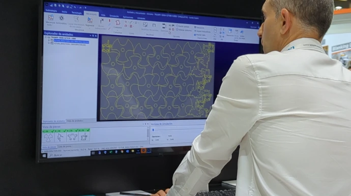
Specialized 3D simulation for fluids and anti-collision
Preview the process and prevent production errors
The simulation validates trajectories, head movements, and cutting sequences before sending the program to the machine.
This verification reduces the risk of collisions, programming errors, and material waste in actual production.
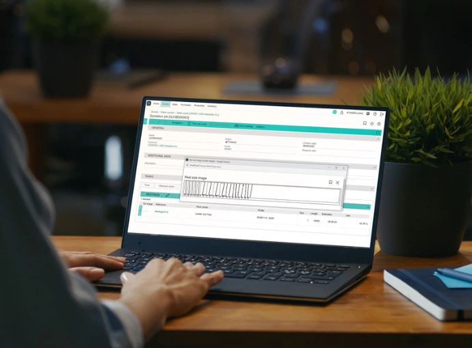
Total connectivity in the industrial plant
Waterjet connected with ERP/MES/CAM systems
Automatic registration of cut parts, tracking of abrasive consumption, complete traceability. Control of materials used, reports, and statistics.
This connectivity is part of the digital environment of Lantek Control Panel and Lantek MES, enabling real-time monitoring of production, machine performance, and resource consumption.

Support, quality, and maintenance
Long-term system performance
An industrial waterjet environment requires specialized support, technical training, and regular software updates.
This ensures compatibility with new materials, machine configurations, and evolving production requirements.
Lantek offers:
A specialized module for optimizing the sheet metal process

Advanced CAD/CAM for sheet metal waterjet cutting
Real hydraulic control. Consistent quality.
- Machine-specific technology tables with automatic adjustment of pressure, abrasive flow, and speed based on material and thickness. It allows for the definition of up to five cutting quality levels to balance productivity, finish, and cost.
- Automatic speed reduction at corners and direction changes, maintaining cutting precision and avoiding unwanted deviations or rounding.
- Dedicated piercing strategies, including configurable circular piercing.
- Taper compensation and trailback control for consistent tolerances.
- Advanced nesting, including multi-head support on X and Y axes.
- 3D simulation of cutting sequences to prevent errors and anticipate machine behavior.
The result is a clean, stable, and repeatable cut, even in sensitive materials like aluminum, stainless steel, copper, or composites. It is suitable for prototypes, short production runs, and high-value parts, with full integration across CAD/CAM, MES, and ERP systems.
Case studies in waterjet cutting for sheet metal
Frequently asked questions about waterjet cutting
These are some common questions about our company.
Waterjet cutting allows for simultaneous cutting through multiple materials without altering their properties or generating burrs. This makes it ideal for pre-assembled sets, coated parts, or composite structures, eliminating intermediate processes and improving the accuracy of the final result.
Pressures above 4,000 bar improve cutting speed and edge quality, especially in thick or hard materials. Incorrect settings can increase wear or abrasive consumption, so parameter control is essential.
CAD/CAM software optimizes paths, adjusts parameters such as speed and abrasive flow, and simulates the process before executing it. This reduces errors, improves edge quality, and maximizes material utilization. Additionally, it facilitates integration with ERP and MES systems.
Piercing strategies should be adapted to material type, thickness, and geometry. Proper configuration ensures clean entry points and prevents defects.
Common errors include incorrect parameter configuration, lack of machine-specific setup, and poor maintenance planning. Integration with the digital production environment is also essential.
The system records data for each part, including materials, cutting conditions, time, and consumption. This supports quality control and cost analysis.
Efficient nesting reduces waste, minimizes spacing between parts, and improves material utilization, which directly lowers cost per unit.
Yes. A multi-technology CAD/CAM system allows programming different types of machines from a common environment, without duplicating processes. This simplifies management, facilitates planning, and reduces programming time in mixed production environments.
The main factors are abrasive consumption, water usage, cutting speed, and system maintenance. Adjusting these parameters from the software, according to the type of piece, allows for cost reduction without compromising quality.
Sheet metal systems include machine-specific technology tables, automatic parameter control, and strategies for maintaining quality in corners and complex geometries..