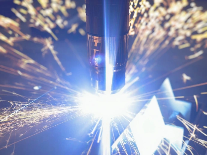
What is plasma cutting and how does it work?
Thermal cutting with an electric arc and ionized gas
It is one of the most common industrial cutting technologies because of its speed, cost control, and ability to work with different materials and thicknesses. It can also be connected to CAD/CAM software and MES systems for traceability, production monitoring, and shop floor control.
Types of plasma cutting
Choose according to cut quality, speed, and thickness:
Conventional plasma
Uses a standard power source with basic control of arc quality. Suitable for fast cutting in medium thicknesses.
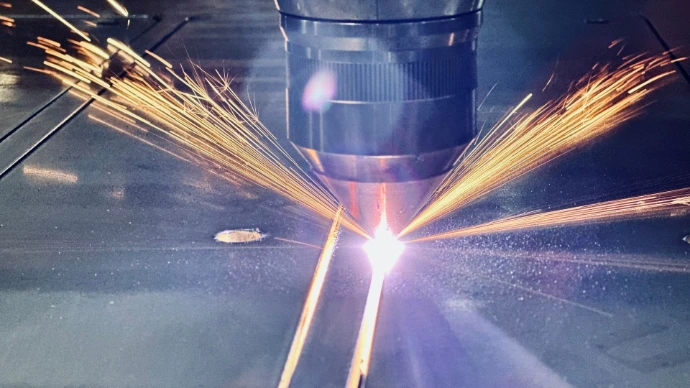
Technology True Hole
Automatically improves bolt holes in steel, increasing accuracy and roundness.
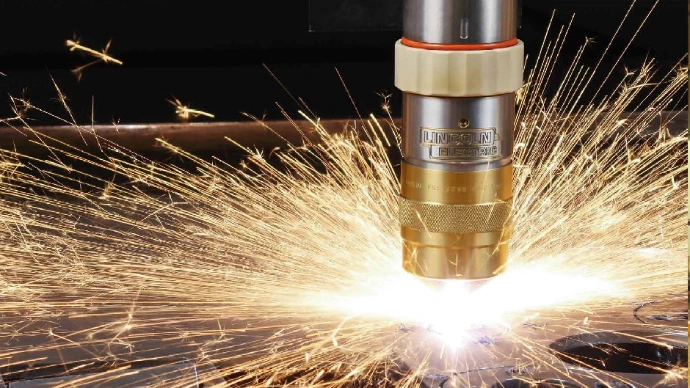
High-definition (HD) plasma
Uses advanced plasma technology to deliver cleaner, more accurate cuts with less slag. Suitable when finished part quality is a priority.
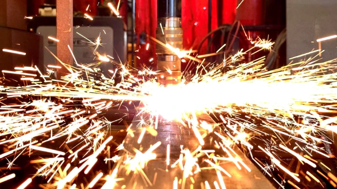
CNC plasma cutting with process control
Connection with CAD/CAM systems for sheet metal and specific 3D solutions for tubes, pipes and structural profiles.
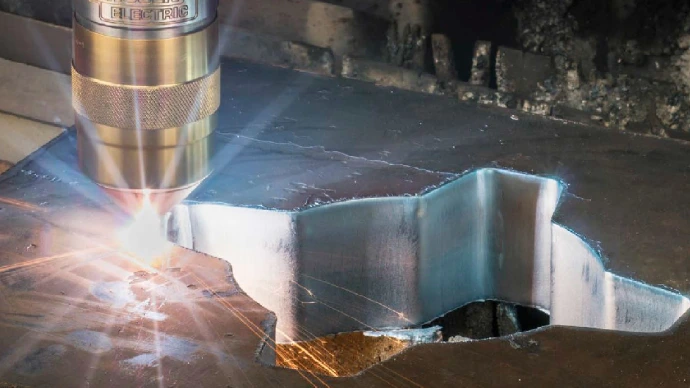
CNC plasma software guide
Program, simulate, and control your production
It can also connect with CAD, ERP, and MES systems to support traceability, production planning, inventory control, and shop floor monitoring. Choosing the right plasma cutting software helps improve machine use, reduce errors, and limit non-productive time.
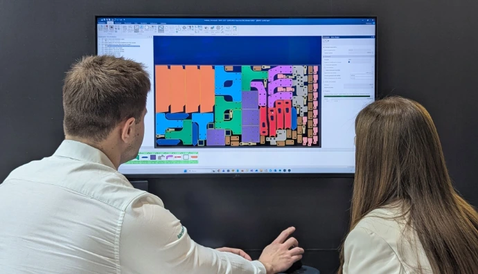
Nesting for irregular parts and remnants
Make better use of each remnant, reduce material consumption, and improve profitability
Automatic nesting is essential in plasma cutting. The software must utilize irregular remnants, apply rules based on sheet metal type, and control thermal margins and cutting priorities. This improves material yield and reduces both material and gas costs.
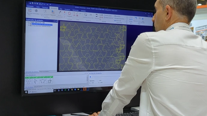
Advanced simulation and collision detection
Detect errors before cutting and protect your machinery
Compatibility with multi-axis systems, rotary heads, and beveling
Complex cuts in a single pass, with less manual intervention
Support for industrial marking and auxiliary processes
Cutting, marking, and auxiliary operations within the same workflow

Connection with ERP/MES and full process traceability
Connect the technical office and the shop floor in real time

Modularity for growing plants
Your software can grow with your plant without replacing the entire system
Plasma cutting software should allow companies to add new functions without changing the full system. This may include tube cutting through dedicated 3D solutions, advanced nesting, QR code reading, DNC communication, or connection with new machines. This supports production growth while protecting operational continuity.
Lantek offers
Two specialized modules for sheet metal and structural cutting processes
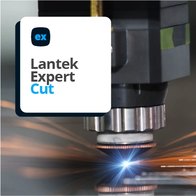
Specialized CAD/CAM for plasma cutting in sheet metal
Thermal control. Stable production. High material use
Lantek Expert Cut is CAD/CAM software for CNC plasma cutting machines, designed to work with thin and thick sheet metal while supporting thermal stability, repeatability, and industrial performance.
The system supports advanced technological elements such as bevels, loops, and bridges, which can be assigned manually or automatically according to material and thickness. It also manages different head types, and tool changes to maintain suitable cutting conditions.
Key functions include:
Micro-cuts and bridges to hold parts and reduce piercing time.
Multi-head and multi-torch management with nesting.
Bevels using rotary torches or triple heads for welding preparation.
Industrial marking by powder, ink, punching, cutting, drilling, or sealing.
Automatic or manual evacuations and skeleton management.
3D simulation of the real cutting sequence to prevent thermal errors, collisions, and production stops.
It is suitable for boiler making, metal structures, and medium-series manufacturing where speed and cost per part are key factors.
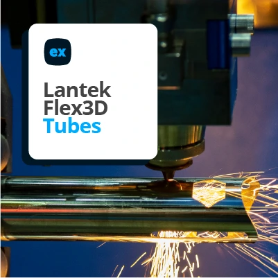
CAD/CAM for plasma cutting in tubes and structural profiles
Welding preparation, beveling, and multi-axis control on one platform
For tubular parts and structural profiles, Lantek offers a specialized 3D CAD/CAM environment for light tubes, industrial piping, and structural steel profiles within the same workflow.
The system allows users to:
Program round, square, rectangular tubes, as well as open profiles.
Create full or partial bevels, bevels, and welding preparations.
Generate holes of different shapes and angles, through or blind.
Manage intersections between tubes and profiles with automatic calculation.
Project 2D geometry onto 3D surfaces.
Copy operations in a linear, circular, or grid patterns.
Work with roller or spindle fastening systems.
It also includes integrated management of bridges, micro-cuts, and cutting qualities, together with full 3D simulation of the process to prevent errors before production reaches the machine.
This approach is ideal for HVAC, industrial piping, welded structures, and advanced metal fabrication that requires accuracy, beveling, and repeatability without intermediate manual processes.
Success Stories in Process Improvement with Plasma Cutting Machines
Frequently asked questions
Clear answers to common questions about plasma metal cutting.
Mainly DXF and DWG, as well as STEP, IGES, and other CAD formats depending on the configuration.
Good software goes beyond toolpath generation. It manages thermal variables, nesting with remnants, multi-axis tools, cutting parameters, consumables, and connections with plant management systems. This helps reduce waste, errors, and consumable use.
Torch height control, automatic cutting parameters, correct lead-ins and lead-outs, and machine-specific compensation are key. Lantek Expert applies compensation rules to support more consistent edges.
Lantek Expert applies automatic compensation to achieve smoother and more consistent edges.
Cost calculation should include cutting time, gas, electricity, consumables, material, machine use, and labor.
ERP or quoting software can use these values to avoid underestimating long production runs.
Lantek iQuoting calculates prices based on cutting parameters and material data
Yes. Lantek allows parameter configuration by material, thickness, geometry, and machine technology.
Yes. Lantek Flex3D is designed for tubes, pipes, and structural profiles.
Yes, Lantek provides specialized support according to machine type and cutting technology.
Yes. Lantek supports connection with management and shop floor systems.
Yes, with compatible and open software such as Lantek, which supports more than 4,500 machine models and 90 manufacturers..
The plasma cutting is especially effective for working with aluminum, carbon steel, stainless steel, and other conductive metals of medium and high thickness. It is also possible to cut copper or brass with specific adjustments.
Its speed and cost per cut make it a practical option for large or structural parts.
It depends on the machine and power source, but CNC plasma can generally cut metals up to 50 mm or more with acceptable quality.
HD plasma offers greater accuracy, less slag, better edge quality, and more defined holes, making it suitable for more demanding applications.
Regular replacement of consumables such as electrodes and nozzles, cleaning of the cutting table, torch calibration, and inspection of the fume extraction system.
It is the power source that ionizes the gas. Its quality directly affects arc stability, cutting speed, and cut accuracy.
Not always. Tube and profile cutting usually requires rotary accessories or specific machines, combined with 3D software such as Lantek Flex3D Tubes.
No. Plasma nesting must consider slag areas, larger minimum distances between parts, heat input, and more tolerant geometries. This requires specific nesting algorithm.
Plasma-specific software controls parameters such as gas type, lead-ins, lead-outs, variable speed, piercing times, torch height, and thermal zone management. This improves cut quality and production performance.
Open systems such as Lantek Expert allow users to connect machines from different manufacturers, including both legacy and new equipment, within a single working environment.
Yes, when the CAD/CAM software is connected to the plant network or linked with MES or ERP systems.
Good software goes beyond toolpath generation. It manages thermal variables, nesting with remnants, multi-axis tools, cutting parameters, consumables, and connections with plant management systems. This helps reduce waste, errors, and consumable use.
Plasma is a suitable choice when the priority is material range, low cost per cut, and the part does not require the fine tolerances normally associated with laser cutting. It also offers higher speed than oxy-fuel cutting and a lower initial investment than laser for thicker materials.
Industries such as structural steel fabrication, heavy plate fabrication, industrial bodywork and mixed-production workshops often prefer plasma cutting because of its performance, flexibility and ability to perform cutting, beveling and marking on a single machine.