


Passa al contenuto

Modifica. Salva. Taglia.


Modulo di disegno CAD: software di disegno specializzato per creare e/o modificare pezzi per il taglio industriale, con tecnologia integrata specifica per lamiera, tubi e profili.


Ti mostriamo come funziona

Disegno e progettazione industriale: migliora i processi con il modulo CAD Drawing di Lantek

Questo modulo è più di un editor geometrico. È una soluzione completa di disegno CAD/CAM 2D e 3D progettata per il taglio industriale. Permette di creare pezzi da zero applicando i criteri di produzione direttamente alla geometria già in fase di progettazione.

Within a single environment, users can draw, edit, assign taglio technology, define attacchi and uscite, fixtures, bevels, and lavorazione cycles, as well as verify and simulate. progettazione and produzione preparation take place at the same time. This is not a general-purpose CAD that requires later adaptation. It is a system where pezzi are designed for taglio from the beginning.


Parla con un nostro esperto 

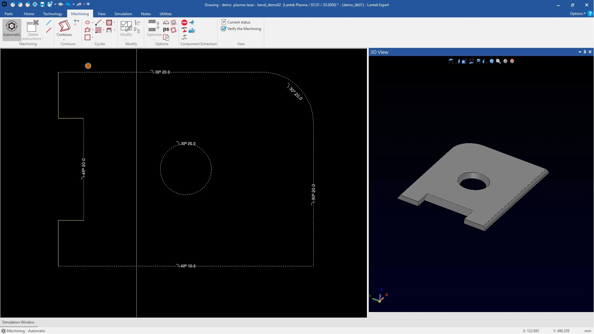
screenshot del modulo di disegno Lantek


Quali problemi risolve questa tecnologia?


Designing pezzi for industrial taglio is not only about geometria. The objective is to ensure that what is designed can be manufactured without rework, file conversions, or unexpected issues on the machine. This modulo closes the gap between progettazione and produzione by combining CAD tools and produzione functions in a single environment.

Dipendenza da sistemi CAD esterni non progettati per il taglio

Many workflows start with general-purpose CAD tools that do not include lamiera or taglio logic. This requires exporting, cleaning, and reinterpreting geometria before produzione. The modulo reduces this dependency by enabling direct progettazione in a CAD/CAM environment adapted to taglio processes. Fewer conversions reduce errors and preparation time.

Visibilità limitata prima del taglio


Sending pezzi to the machine without prior validazione introduces risks. Sequence errors, overlaps, or geometric conflicts lead to material waste and delays. 


The modulo includes verification and simulazione tools within the drawing environment, allowing users to review both geometria and lavorazione before produzione.

Geometrie importate da pulire


DXF and other file formats often contain open contours, duplicates, or poorly structured elements. Manual correction takes time and introduces uncertainty. 


The modulo provides editing, detection, and validazione tools to clean and prepare geometria directly, leaving pezzi ready for lavorazione without additional software.

Regolazioni di produzione tardive


In many systems, decisions such as attacchi, clamps, or corner treatments are defined during lavorazione. This separates progettazione from produzione and increases inconsistencies. In this modulo, these parameters are defined during progettazione. Users can assign attacchi, microgiunzioni, loops, and taglio technologies from the start.

Vantaggi tecnici e operativi


Progettazione + tecnologia

in un unico ambiente

geometria and produzione parameters are defined together. Users can assign attacchi, fixtures, loops, and taglio strategies while designing the pezzo.


Strumenti nativi

per il taglio industriale

Includes functions developed for lamiera, tubo, and profilo taglio, such as hole destruction, pattern layouts, and microgiunzioni, which are not available in standard CAD systems.


Validazione e simulazione

prima della produzione

Verify lavorazione strategies, simulate taglio sequences, and detect conflicts before sending the job to the machine.

Where to find the Drawing modulo in the Lantek ecosystem


The CAD Drawing modulo is available across Lantek CAD/CAM solutions. It includes libraries, attacchi, fixtures, and finishing options adapted to each produzione process, including lamiera taglio, tubi, and profili.


Discover our solutions

CAD/CAM for laser taglio, plasma, and other technologies

CAD/CAM for duct and lamiera development

CAD/CAM 3D for tubo taglio machines

CAD/CAM 3D for structural profilo taglio

Funzionalità principali


Geometric creation for taglio pezzi


The drawing environment enables the creation of complete 2D geometria, including lines, arcs, circles, polygons, grooves, and standard industrial shapes. geometria is structured from the beginning for lavorazione, simplifying the assignment of taglio technology and sequences.

Advanced lead-in and lead-out management


The modulo includes full control of attacchi and uscite, with automatic, semi-automatic, and manual options. Users can define how the tool enters and exits each contour to improve edge quality and pezzo stability.


microgiunzioni and pezzo holding strategies


microgiunzioni are defined during progettazione. The system allows different types of fixtures, nano-joints, and parameterized microgiunzioni to maintain pezzo stability during taglio and reduce deformation.


Loops and corner control


Automatic loop generation, edge rounding, and vertex control improve taglio quality in critical areas. Users can apply these settings globally or selectively.

2D and 3D smussi


The modulo supports standard smussi and 3D smussi with control over upper and lower faces and contour connections. This is essential for pezzi requiring welding preparation or edge finishing.


taglio technologies integrated into progettazione


Users can assign technologies such as marking, no-cut areas, clean taglio, or dynamic taglio directly in the drawing phase. This ensures consistency between progettazione and produzione.


Automatic cycles and hole destruction


The modulo includes linear, circular, and irregular cycles, as well as manual, automatic, and semi-automatic hole destruction functions. These tools are designed to optimize machine times and resolve repetitive operations directly from the progettazione. It also allows for the lavorazione of pattern layouts and complex sequences without external programming.


Operation recognition from imported geometria


The system allows the assignment of lavorazione operations such as drilling, threading, or milling directly on imported geometries, converting shapes into produzione instructions.


Dimensional compensation


Tools are available to adjust pezzo dimensions at specific points to compensate for welding or thermal deformation. These adjustments are applied directly in the progettazione without rebuilding the pezzo.


Need more? We have the solution.


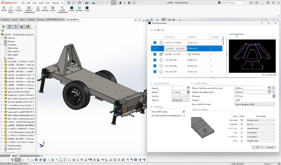
Lantek offers software mechanisms to transfer CAD drawings from well-known CAD systems such as SolidWorks®, SolidEdge®, Inventor®, Catia®, NX, and PTC® Creo® to perform the automatic unfolding of any lamiera progettazione in three dimensions. It is an ideal solution to integrate the user's three-dimensional models with Lantek's solutions. It is a powerful, direct, and intuitive way to avoid unnecessary file generation.

Additionally, Lantek seeks collaboration agreements with software modeling companies to achieve the best possible integration with their CAD systems.


See Lantek Flex3D Addins

Domande frequenti


It is a complete 2D and 3D drawing software within Lantek Expert, with sufficient creation and editing tools to progettazione pezzi from scratch, not just to 'fix a DXF'. You can draw common geometries (lines, polylines, arcs, circles, rectangles, polygons, slots, ellipses, etc.), transform them (copy, move, stretch, rotate, scale, symmetry) and build contours ready for produzione. The difference compared to a general CAD is not that it 'draws more', but that it does so with taglio and lavorazione in mind: from the progettazione itself, you can incorporate typical industry decisions and review the result before moving to produzione.

Yes. The modulo includes a wide range of 2D drawing tools to create geometria from scratch with precision, using a mouse or point input. Additionally, the 'point access' allows you to snap to exact references (end, middle, intersection, tangent, quadrant, center, projected, etc.), which is key for technical pezzi where millimeters matter. In practice, this allows the modulo to function as an independent pezzo designer for many use cases in the industry, without the need for other software for day-to-day tasks.

It is not limited to geometria. It includes Technology and lavorazione menus within the Drawing modulo itself, with specific functions for industrial taglio. For example, you can manage attacks (entries/exits) with automatic or semi-automatic insertion, define fixtures and nano-joints, generate loops in corners and 'kill edges', assign technologies such as clean taglio, marking, not taglio, dynamic taglio, and no partial taglio, or create auxiliary geometria and mesh patterns. These are decisions that in a generic CAD often remain outside or require plugins and additional steps. Here, they are pezzo of the natural progettazione flow.

The modulo supports automatic, semi-automatic, and manual lead-in strategies with multiple configurations. This helps improve cut quality and reduce defects such as burrs or marks.

The modulo includes a specific section for Anchors to introduce micro-holdings, with options to delete, choose different types, configure parameters, and move the entry or exit point of the anchor. It also includes a nano-joint, which reduces power to leave an anchor-type holding without entry or exit, useful for preventing small pezzi from shifting or falling. You can even 'convert to geometria' certain micro-holdings to treat them as geometria when needed. This is not a minor detail: in actual taglio, the stability of the piece defines quality, safety, and repeatability.

It includes Loops with automatic insertion in corners of closed geometries (depending on configuration), manual insertion of loop types, parameter configuration, and semi-automatic options for rounding edges in contours. It also includes 'edge killing', which introduces rounded angles at vertices. In taglio, corners are where many visible defects appear: overheating, marks, vibration, or imperfections. Being able to control loops and vertex treatment from the progettazione itself allows you to anticipate the problem instead of chasing it on the machine.

Yes. There are standard Chamfer tools to add, modify, invert smussi, and assign variable smussi to complete contours, in addition to parameter configuration. There is also a 3D smussi section where you define the bottom face, connections between the upper and lower face contours, and how lavorazione should respect those connections, supported by updating the 3D view during the definition. This is relevant when the chamfer is not 'decorative', but functional for welding, assembly, or edge preparation.

Users can define marking, no-cut zones, clean taglio, and other strategies directly in the progettazione. This ensures that the pezzo includes produzione intent from the beginning.

In lavorazione, you have options for automatic lavorazione, insertion of rapid movements, taglio movements, and a powerful block of contours (manual and automatic), as well as actions like lavorazione all marking, all taglio, or all taglio of a certain quality. There are also cycles (linear, circular, irregular, grid) defined by points, distances, number of points, etc. And specific functions such as rapid taglio in holes, manual hole destruction, automatic destruction (depending on the type of machine), and semi-automatic destruction with modes (grid, spiral, continuous). For many pezzi, this reduces manual work and standardizes results.

The modulo includes pezzo inspection (checking the pezzo, detecting a pezzo to 'obtain' a clean pezzo from another and removing excess geometria), measurements (viewing geometria, distances and angles, angles by three points) and lavorazione verification to ensure everything is machined, that there are no overlaps, and that attacks, micro-holds, or loops do not interfere with other elements. Additionally, you can simulate program instructions, move along the line position, advance and retreat, and 'process' the simulazione including rapid movements and evacuation. In practical terms: you reduce surprises. simulazione and verification are the filter before the error becomes cut metal.

Contattaci


Ho letto e accetto le note legali e la privacy policy

Grazie per il tuo feedback!

Il nostro team risponderà al tuo messaggio il prima possibile.

Nel frattempo, ti invitiamo a visitare il nostro sito web.